|
 1x
DIL28 socket 1x
DIL28 socket
1x DIL16 socket
1x 24LC256
1x PIRA32
Microcontroller
1x MAX232CP
1x LM567
1x TLC272CP
1x PCF8563P
1x 7805
2x 1N4007
2x 1N4148
2x LED 5mm white
1x 4.332 MHz crystal
1x 32.768 kHz crystal
1x Coil 09P-331K radial (0.33 mH)
1x Coil 09P-152J radial (1.5 mH)
1x Signal relay 5x10 mm (submini) or 7.5x12.5 mm, 5-6 V
1x CR2032 battery holder vertical
1x Lithium battery CR2032
1x CANON 9 female 90 deg.
2x jumper
1x power supply connector
2x BNC connector 90 deg.
Resistors:
18x 2k (1%)
7x 10k (1%)
4x 33k (1%)
3x 15k (1%)
1x 4k7 (1%)
1x 91R
1x 150k
1x trimmer 1k 10mm (PT10)
1x trimmer 5k 5mm (PT06)
1x SIL resistor network 3x 1k (2%, discrete)
1x SIL resistor network 4x 1k (2%, discrete)
Capacitors:
4x 1u/63V (E)
2x 100u/25V (E)
9x 100n (C)
2x 10u/50V (E)
2x 100u/16V (E)
3x 22p (C)
3x 4n7 (P)
1x 22n (5%, P)
1x 3n3 (P)
1x 220n (P)
2x 1n (C)
1x 47n (5%, P)
1x 330p (C)
1x 4u7 (P, RM=5mm)
 The LCD display can be connected to any
PIRA32 RDS encoder module regardless of date of production. It requires firmware version 1.5b or later. The LCD display can be connected to any
PIRA32 RDS encoder module regardless of date of production. It requires firmware version 1.5b or later.
Description and
schematic diagram
PCB layout
Part list:
U1 - MCP23008
C1 - 100n (ceramic)
R1 - 10R
R2 - trimmer 10k
J1 - HD44780 based LCD module 16x2
J2 - jumper
 Description Description
PCB layout
Schematic diagram
Part list:
U1 - MRDS1322
R1, R2, R3, R4, R5. R6, R7, R8, R9, R22, R27 - 2k 1%
R10, R11, R12, R13, R14, R15, R16, R17, R19, R21 - 1k 1%
R18, R23, R24 - 10k
R20 - trimmer 1k
R25, R26 - 22k 1%
C1, C2 - 22p (ceramic)
C3, C4 - 100n (ceramic X7R)
C5 - 27n (plastic foil)
C6 - 10n (ceramic X7R)
L1 - 330 uH
Y1 - crystal 4.332 MHz
D1, D2, D4, D5 - BAT54 SOT23
D3 - Zener 6V2 SOT23
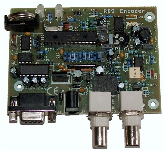
PIRA32 RDS Encoder
If you decide for the RS232 connection, the RDS
encoder is connected directly to PC via standard serial cable terminated by CANON D-SUB
female/male plugs. You can find full connection diagram in pdf manual provided on these
pages.
Pin assignment as can be found on the devices:
Wire
description |
PC COM |
RDS Encoder |
9-pin
male |
25-pin
male |
9-pin female |
9-pin male |
Data from PC to
RDS encoder
(forward channel) |
3 |
2 |
3 |
2 |
Data from RDS
encoder to PC
(feedback channel) |
2 |
3 |
2 |
3 |
| Signal ground |
5 |
7 |
5 |
5 |
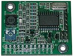
MicroRDS Encoder
See the information provided in the micrords.pdf.
|