 Why is it important to use this device?
| Pira CZ Compressor/Limiter/Clipper for FM broadcasting |
Why is it important to use this device?
Audio signals as music or speech have big dynamic ranges. There are silent and loud sections. These audio signals aren't too good for a transmitter, which requires audio signal with constant level on the input. Limiter is a device, which weakens loud signals and intensifies silent signals. On its output there is signal with constant level. Signal clipping on the limiter output allows to increase the signal level without exceeding maximum frequency deviation limit 75 kHz. It's very suitable since preemphasis is used.
If your transmission chain does not include any similar device, you should build this one. You will be surprised by its quality, efficiency and simplicity. This is the Pira CZ Compressor/Limiter/Clipper.
Be careful if you want to buy any simple compressor/limiter board available on the market! Although a big list of features is mentioned, some of these toys have no signal overshooting protection and have no precise preemphasis with HF clipping option. With these devices it's not possible to keep loud sound AND meet the frequency deviation limit. So there is no reason why to pay for them. The device should guarantee basic technical characteristics of the modulation signal, nothing more - no equalizers and other disutilities.
Characteristics:
| Supply voltage: | 9-16 V |
| Quiescent supply current (12 V): | 15 mA |
| Output voltage: | linear adjustable 0-3.5 V p-p (0-1.2 V rms) |
| Lower cut-off frequency (3 dB): | input: 25 Hz, output: <2 Hz |
| Upper cut-off frequency (3 dB): | 14.5 kHz |
| Min. input voltage: | 0.6 V p-p (0.2 V rms) |
| Input impedance: | 5000 ohm |
| Output impedance: | 500 ohm |
| Signal-to-noise ratio: | >70 dB |
Schematic diagram:
Part list:
R1, R3 - 10k
R2 - 1k
R4, R5 - 1M
R6 - 18k
R7, R8, R15, R16, R17, R19 - 33k
R9 - 1M5
R10, R12, R14, R18 - 470R
R11 - 270R
R20, R23, R25 - trimmer 5k
R21 - trimmer 5M
R22 - trimmer 1k
R24 - trimmer 500R
C1 - 4n7 (EU) or 6n8 (USA), plastic
C2 - 470n plastic
C3, C6 - 4n7 plastic
C4 - 330n plastic
C5, C7, C8, C12 - 10n ceramic
C9 - 330p ceramic
C10 - 470p ceramic
C11 - 82p ceramic
C13 - 10u/25V tantalum
C14 - 470u/25V electrolytic
C15, C16 - 220u/10V electrolytic
U1 - TLC272
U2 - 78L05
Q1 - BC557B
Q2 - BF245C
D1, D2 - Red!!! LED diode 5 mm,
medium luminance (eg. 200 mcd)
J2 - jumper
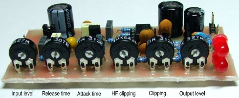
Adjusting elements description:
Preemphasis on/off - Connect (close) the jumper to turn on the preemphasis - recommended just here.
Attack time, release time - Compressor/limiter time constants. The attack time should usually be small, the release time determines the signal processing intensity.
Clipping, HF clipping - Recommended adjustment procedure: 1) Set the HF clipping to the lowest (turn left), set the Clipping closely below clipping level of low frequencies (1 kHz and lower). 2) Adjust HF clipping on a common program content. Check the sibilancy (hiss) reproduction - no distortion should be audible. The more clipping the more signal loudness.
Input level - Gate function analogy. If set right, background sound (noise, hum) present in original signal is not amplified and clipping is working on all common program content.
Two LED diodes indicate the clipping. Very short peak clipping may not be visible - the indicaton is only a secondary function of the LEDs, the main function is to realize the signal clipping and overshoot protection.
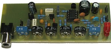
PCB:
Top side.
Bottom side.
Bottom side (incl. CINCH input connector).
Stereo version available here.
Output signal characteristics measured:
Illustration of clipping and output filtering
quality. Signal 2 kHz, Clipping set to maximum.
Signal 1 kHz, Clipping set closely below clipping
level.
Signal 1 kHz + 10 kHz, HF clipping set to
minimum, Clipping set as above.
Signal 1 kHz + 10 kHz, HF clipping set to
maximum, Clipping set as above.
(C) 2008 Pira CZ. Commercial use is forbidden!