 Technical
specifications:
Technical
specifications:| PLL tuning |
Technical
specifications:
Dual-speed PLL designed for wideband FM transmitter.
Power supply: 8-15 V stabilized, 40 mA
Frequency range: 82,5-108 MHz
Step frequency: 100 kHz
RF input voltage range: 10-500 mV
RF input impedance: 135 ohm
Schematic diagram:
Pin meaning:
1 - tuning voltage (output)
3 - RF signal from oscillator (input)
2, 4 - ground
Tl1 - reset
Parts list:
Capacitors:
C1, C12 - 2,2 nF (ceramic)
C2, C9 - 10 nF (ceramic)
C3 - 47 uF (electrolytic)
C4 - 10 uF (tantalum)
C5 - 0,47 uF (electrolytic)
C6, C11 - 100 nF (ceramic)
C7 - 1 nF (ceramic)
C8 - 220 uF (electrolytic)
C10 - 22 pF (ceramic)
Resistors:
R1 - 1k
R2 - 4k7
R3, R4, R5, R7 - 10k
R6 - 1k (optional)
R8 - 47k (optional, see below)
Misc.:
IC1 - SAA1057
IC2 - PIC16F84 (programmed) + socket
IC3 - 78L05
X1 - 4 MHz crystal
D1 - LED diode (optional)
Tl1 - button (optional)
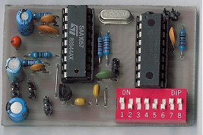
jumpers or DIP switches
Software for the IC2:
pll16f84.asm, pll16f84.hex.
Oscillator type: RC, watchdog: ON.
Jumpers/DIP switches setting: see pllfreq.txt or download user-friendly program!
Instructions
The Tl1 button resets the unit. Press it after frequency set. The unit provides a reset
on power-up, so you don't need to use the button.
The D1 LED indicates the tuning cycle is done (after one second from reset). It's not
needed to use it and the R6 resistor.
The R8 resistor provides a minimal voltage of about 2 V on the PLL output. Use this
resistor if the transmitter's oscillator doesn't work if the tunning voltage is below this
value (mainly after power-up). Place the resistor over the R3.
Notes:
PCB layout
PR = wire-bridge