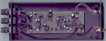
| Stereo encoder with limiter |
Obsolete!
New design is available at http://pira.cz/eng/
This solid stereo encoder is more than a "stereo bug". It can be used for
quality stereo broadcasting.
The limiter ensures right modulation level for very wide input audio level range. Output
amplifier allows to connect the stereo encoder directly to MPX or mono input of a
transmitter.
To assemble and set-up this stereo encoder some experiences are needed.
Technical parameters
Supply voltage: 11-15 V stab.
Supply current: 40 mA
Output MPX voltage level: adjustable 0-8 V p-p
Schematic diagram
Part list
R1, R11 - pot. 10 k
R2, R12, R25, R30, R32 - 47k
R3, R7, R13, R17, R34 - 10 k
R4 - 180 k
R5, R15 - 47
R6, R16 - 240 k
R8, R18 - 82
R9, R19 - 330
R10, R20 - 2,2 k
R14 - trimmer 500 k
R21 - 1.5 k
R22 - 820
R23 - 10 M
R24, R29 - trimmer 10 k
R26 - trimmer 50 k
R27 - 2.7 k
R28 - 150 k
R31 - 470
R33 - trimmer or pot. 50 k
R35 - 10
C1, C3, C11, C13 - 1 u
C2, C12, C29 - 220 p
C30, C35 - 1 n
C4, C14 - 1 u / 25 V tantal.
C5, C15, C25, C27, C28, C31, C33, C34, C43 - 10 u
C6, C16 - 220 n
C41 - 33 n
C8, C18, C23, C24, C39 - 100 n
C9, C19 - 18 n
C10, C20 - 3.3 n
C21, C26 - 10 n
C22, C42 - 100 u
C32, C44 - 1.8 n
C36 - 10 p
C37 - 47 p
C38 - 22 u tantal.
C40 - 220 u
T1, T3 - BF245C
T2, T4 - BC556B
IC1, IC2, IC4 - LM386
IC3 - BA1404
D1 - 1N4007
D2 - Zener diode 2.7 V / 0.5 W
X1 - crystal 38 kHz - buy here
socket 2x3
For increasing the output level connect 10 uF capacitor between Gain pins on the IC4.
C5 and C15 are not required if the audio source is strong enough (usually is).
Setting-up
Now is the device set-up. You can adjust MPX level by R33 at any time.
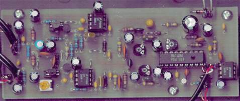
PCB
PR = wire bridge