| RF part 3 W |
Technical specifications
Power supply: 12 V stab., 0,7 A
RF power: 3 W
Impedance: 50-75 ohm
Frequency range: 88-107 MHz
Modulation: wideband FM
Schematic diagram:
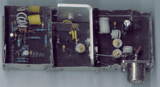
Parts list:
Capacitors:
C1 - 4,7 uF (electrolytic)
C2 - 0,22 uF (electrolytic)
C3, C4, C12 - 100 pF (ceramic)
C6, C9, C11, C13, C14, C19 - 1 nF (ceramic)
C7, C8 - 10 pF (ceramic)
C10 - 8.2 pF (ceramic)
C18 - 22 pF (ceramic)
C15 - trimmer 47 pF
C16, C17 - trimmer 60 pF
C20, C5 - 100 nF (ceramic)
C21 - 470 uF (electrolytic)
Coils:
(All coils are free-standing air-core types, wound of 0,7 mm Cu wire, 6 mm internal
diameter.)
L1, L6 - 4,5 coils
L3 - 2,5 coils
L4 - 1,5 coils
L2 - 6,5 coils around R9 resistor
L5 - 9,5 coils
L7 - 3,5 coils
Resistors:
R1 - 10 k pot.
R2 - 4,7 k
R3, R4, R5, R8, R10 - 27 k
R6, R16 - 10 k
R7, R15 - 470
R9 - 100
R11 - 270
R12 - 1 k
R13 - 43
R14 - 10
Diodes:
D1, D2 - BB109G, BB409 or BBY31
Transistors:
T1 - BC547C (BC548C, BC547B)
T2 - BFR91A (BFR96)
T3 - BFR96S
T4 - 2SC1971
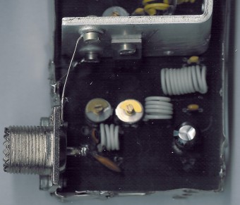
Output stage with 2SC1971
Tuning
Connect two 24 V / 3 W bulbs in parallel to the output and set the right frequency on PLL. Now turn on the transmitter. You should tune it on a receiver. Maybe you might stretch coils of the L1. Fix the L1 in position when the tuning voltage (on C4) is in range 4-9 V. Then use C15, C16 and C17 to adjust the highest power (the highest light of the bulbs). Then you can connect antenna and audio signal. Adjust R1 until the audio sounds as loud as the other stations.
With good antenna (dipole placed outdoor and high) the transmitter has very good coverage range about 1500 meters, the maximal coverage range is up to 20 km.